SUIVEZ-NOUS:
-
Hangzhou, China
Membrane Switch Design Guide
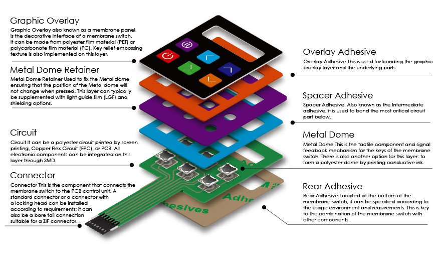
Designing a membrane switch necessitates a holistic consideration of both customer requirements and the application environment to ensure product stability and durability. Evaluation is key when it comes to anticipating the range of temperature and humidity, UV exposure, and potential corrosive substances. These factors must be thoroughly considered in material selection and structural design to ensure product performance meets application demands. For the basics of membrane switches you can read this article ” What is a membrane switch? How do membrane switches work? “.

Graphic Overlay:
- Design of the Graphic Interface: The visual presentation on the membrane panel, including patterns, text, and symbols, is crucial. It serves dual purposes: enhancing aesthetic appeal and ensuring an intuitive user interface. Designers should consider color schemes, layout of graphics and text, resolution, and line clarity. Utilize professional graphic design software such as Adobe Illustrator or CorelDRAW for precise control.
- Color selection should be carefully executed, preferably using complementary, analogous, or triadic schemes, with a recommended limit of 3-5 colors. Common printing color systems include CMYK, PANTONE, and RAL. You can refer to the article “In-Depth Analysis of Color Systems: Differences and Challenges in Converting RGB to CMYK, Alongside PANTONE and RAL” to gain more insights into the color systems in printing.
- Button Embossing Design: The design of embossed keys on membrane switches is a key technology that helps to enhance user experience and increase product usability. Please refer to “From Membrane Switches to Graphic Overlays: The Selection and Application of Embossed Keys” for more information on the design of embossed keys on membrane switch panels.
- Transparent Windows: Design options for graphic interface windows on the membrane panel include high transparency, diffusion effects, or semi-transparent with various colors.

Circuit Design:
- Matrix Principle Design: Utilize row and column intersections for button operation detection, reducing the number of conductive traces and saving space. Ensure each intersection has a unique identification method to prevent button conflicts or phantom key issues.
- Common Circuit Principle Design: All buttons share a common line, helping reduce conductive trace usage. Ensure the common line is sufficiently wide to handle the current when all buttons are pressed simultaneously.
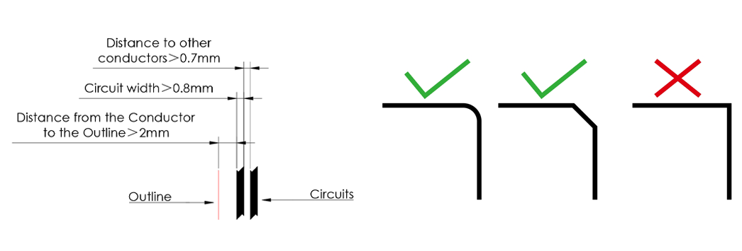
- Circuit Design Rules: Maintain a minimum distance of 0.7mm between the circuit and any conductors, and ensure line width is greater than 0.7mm to reduce resistance. Avoid circuit bridging, design power lines to be as wide as possible, and ensure corners are rounded or at 45-degree angles. Conductive traces should be at least 2mm away from the edges and far from electronic component pads, with a recommended distance of 2mm or more.

Structural Design:
- Metal Dome Tactile Structure Design: As a tactile component in membrane switches, metal domes have a relatively simple structure. Ensure die-cutting on the double-sided adhesive at the button positions, and design exhaust channels between each button to prevent air trapping during assembly. A fixing layer should be added above the metal domes after installation to secure their position.
You can refer to the article “What is a Metal Dome Membrane Switch?” to learn more about metal dome membrane switches. - Upper Circuit Embossing with Dome Structure Design: Utilize a specially designed spherical dome mold for thermal forming on the upper circuit, creating a tactile component for the membrane switch.
- Backlight Construction Design: Design the light guide film (LGF) to transmit LED light to the buttons. Implement light barriers between buttons to prevent light interference or leakage. Learn more about backlit membrane switches.
- Waterproof Construction Design: Seal all layer edges to prevent water ingress. Use waterproof tape or sealant for edge sealing. Opt for waterproof materials and apply an external waterproof coating. Ensure connectors are also waterproofed. Learn more about waterproof membrane switches.

Material Selection:
- Graphic Overlay Materials: PC and PET are commonly used for membrane switch panels. Besides the material itself, the graphic interface surface can be enhanced with various effects such as gloss, matte, anti-glare, and brushed finishes to enhance visual appeal and user experience. Additionally, materials with anti-fingerprint, antibacterial, or UV-resistant properties can be selected to meet specific requirements. Learn more about graphic overlay materials.
- Circuit Materials: The circuit part of a membrane switch can be made from printed silver paste on polyester film, or alternatively, copper flex circuits or aluminum foil circuits can be chosen.Click here to learn more about homoflex circuits.
- Adhesive Selection: A variety of adhesives are available for use in membrane switches, with the selection depending on the application scenario and specific switch structure. Refer to our guide on the use of adhesives in membrane switches for more information.
- Shielding Materials: Shielding is crucial to mitigate the effects of electromagnetic interference (EMI) on circuit performance. This is especially important in high-frequency, precision measurement equipment, and in environments highly sensitive to EMI. Common shielding materials include aluminum foil and conductive ITO. Explore more about shielding in membrane switches.
Component Selection:
- Connector Selection: Connectors play a critical role in linking the membrane switch to the PCB, directly influencing device performance and stability. Check out our detailed guide to choose the right membrane switch connector.
- Metal Dome Selection: As a vital tactile feedback component in membrane switches, metal domes come in various types. Our extensive guide will help you understand and select the best metal dome for your membrane switch.
- LED Selection: LEDs in membrane switches are available as top-emitting and side-emitting types. Top-emitting LEDs come in monochrome sizes like 0603, 0805, 1206, with options for bi-color and tri-color. Side-emitting LEDs are commonly used in LGF membrane switches, also offering bi-color, tri-color, and multi-color options.
Contact WeGlow for all your membrane switch design and prototype manufacturing needs. Learn more about the products.
